# Timers
- What are the functions of a timer?
- What are the components of a timer?
- What is the relationship between the precaler, the count and the match register?
Every microcontroller has timer peripherals. Timers are used to generate precision timing events, which do not involve the processor. In order to achieve this, interrupts are used.
# Basic Timer
Timers are hardware peripherals in a microcontroller which increment an internal value at a given input signal.
Timers have three functions:
- Use the timer as an internal clock to time an activity, such as delaying or a time-triggered event. Pulse-Width Modulation (PWM) control is such an application.
- Capture the activity of an external signal, i.e. how long does it take for a given signal to change under certain conditions.
- Counting the activity of an external signal, e.g. how many pulses can be counted in a given time-frame.
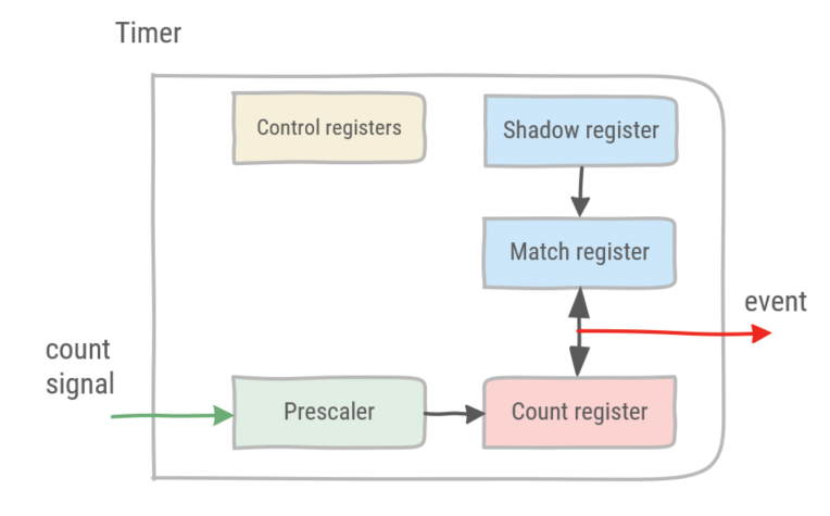
# Components of a timer
In essence, timers consist of a count register, prescaler and match register.
- The count register represents the internal value of the timer, which is incremented each clock cycle or sometimes decremented.
- The prescaler is a divider before the count register. A prescaler combined with the count register, increases the range of the timer. For instance, given a 16-bit count register, values up to 2^16 can be represented. Adding a 16-bit prescaler increases the range of the timer to 2^32.
- The match register sets the threshold value of the timer. When the count register reaches the match value, an update event is generated.
WARNING
The processor can update the match value asynchronously from the timer, even when the timer is running. In order to avoid any glitches, a shadow register is used to store the value until the actual match register can be safely updated with a new value.
TIP
Some timers do not have a match register. Rather, they decrement the count register and upon reaching the value 0, an event is generated.
# Timer example (without interrupts)
The STM32L476RG microcontroller has 12 timers, excluding watchdog timers. TIM7 is a basic 16-bit timer, with a 16-bit prescaler. In the following example, the approx_wait function will be replaced with a timer-based wait, using a fixed period of 1s.
TIM7 has 8 registers, see pages 1174-1178 of the RM0351.
- TIM7_CR1 (control register)
- UIFREMAP: control whether to copy the interrupt flag in the count register
- ARPE: control whether the match register has to be automatically reloaded
- OPM: control to stop counting when count reaches match
- URS and UDIS: control to enable slave mode controller (with multiple timers)
- CEN: starts the counter
- TIM7_CR2 (control register)
- MMS: select master mode (multiple timers)
- TIM7_DIER (interrupt enable register)
- UDA: DMA requests enable
- UIE: interrupt enable
- TIM7_SR (status register)
- UIF: interrupt flag, this flag has to be cleared by the processor to acknowledge the interrupt
- TIM7_EGR (event generation register)
- UG: control to reinitialize the timer counter and prescaler after the update event
- TIM7_CNT (count register)
- This register contains the count value of the timer
- TIM7_PSC (prescaler)
- The prescaler divides the clock frequency by the value+1. Whereas the value is placed in the prescaler register
- TIM7_ARR (match register)
- When the count register and the match register value match, an update event is generated
Configuring TIM7 requires the following steps:
- Enable TIM7 in APB1ENR1
- Set prescaler and match values
- Set event generation, re-initializing the timer counter upon the update event
- Start the timer
In order to wait synchronously, check the interrupt flag bit until it has been set. Do not forget to clear the interrupt flag bit to acknowledge the update event.
TIP
To calculate the values of the prescaler and match register, the oscillator frequency used to drive the timer has to be known. Then the period is determined by:

For instance, given a AHB clock frequency of 48MHz, to obtain a period of 1s, the denominator should equate to 48 000 000. Thus values 1999 and 23999 can be chosen. Keep in mind that both the prescaler and match register are 16 bit register, this these values cannot exceed 2^16. More information on timing control of the microcontroller can be found in RM0351 chapter 6.
// includes low level peripheral definitions
#include "stm32l476xx.h"

/**
 * Initializes PA5 as a digital output
 * */
void led_init(){
    //Enable GPIOA peripheral in the AHB2ENR: set bit 0
    RCC->AHB2ENR |= 1;

    // GPIOA_MODER set GP output mode: reset bit 11 & set bit 10
    GPIOA->MODER &= ~(1 << 11);
    GPIOA->MODER |= 1 << 10;
}

/**
  * toggles PA5
  * */
void led_toggle(){
    // read current state of pin 5
    if(GPIOA->ODR & (1<<5)){
        //GPIOA_BSRR reset pin 5: set bit 21
        GPIOA->BSRR |= 1 << 21;
    }
    else {
        //GPIOA_BSRR set pin 5: set bit 5
        GPIOA->BSRR |= 1 << 5;
    }
}

/**
 * Initializes timer 7 for a period of 1s
 * */
void tim7_init(){
    //Enable TIM7 in the APB1ENR1: set bit 5
    RCC->APB1ENR1 |= 1 << 5;

    // Given a clock of 48MHz, set prescaler and count register for a period of 1s
    TIM7->PSC = 1999;
    TIM7->ARR = 23999;

    // Set event generation,
    // re-initializes timer counter
    // and generates an update of the registers
    TIM7->EGR |= 1;
}

int main()
{
    led_init();

    tim7_init();

    // Start the timer
    TIM7->CR1 |= 1;

    while (true)
    {
        // wait until the interrupt flag has been set
        while (!(TIM7->SR & 1));
        // clear the interrupt flag
        TIM7->SR = 0;

        led_toggle();
    }
}
2
3
4
5
6
7
8
9
10
11
12
13
14
15
16
17
18
19
20
21
22
23
24
25
26
27
28
29
30
31
32
33
34
35
36
37
38
39
40
41
42
43
44
45
46
47
48
49
50
51
52
53
54
55
56
57
58
59
60
61
62
63
64
65
66
67
← Digital IO Interrupts →